The Peak Voltage of an Ujt Is Best Described by
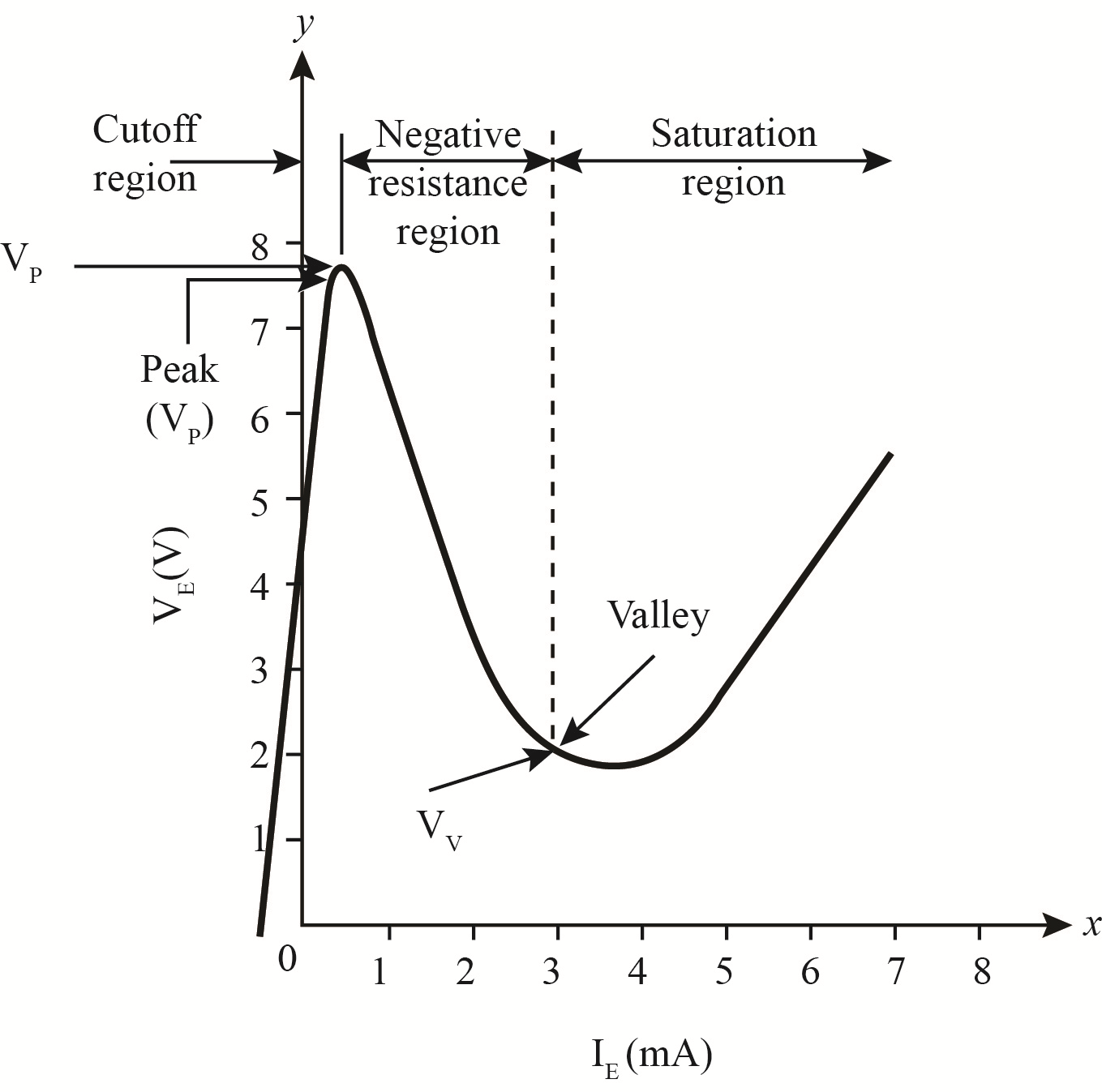
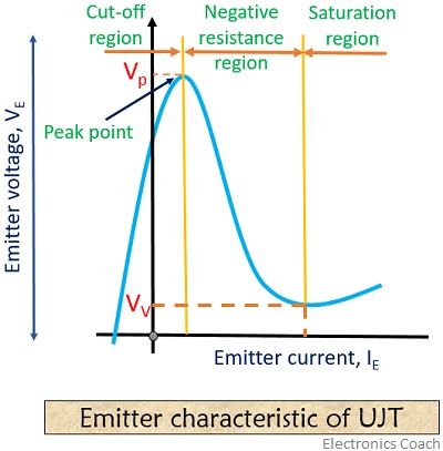
By varying R E we can change the time constant R E C and alter the point at which the UJT fires. Hence the region is called negative resistance region.

Sketch The V I Characteristics Of An Ujt And Describe Some Of Its Important Applications
Q1 Choose the correct or best alternative in the following.
. The lowest current that can prevent the transition of a UJT from conduction to blocking region. The peak point voltage will be determined by the supply voltage VBB and the standoff ratio η. Comment Related Questions on Power Electronics.
This minimum value of the emitter voltage Ve for which the emitter current starts to flow is called the firing voltage of UJT. Determine the peak point voltage for the UJT. See answer 1 Best Answer.
The emitter voltage at peak point is _____. Answer Solution Discuss in Board Save for Later 8. The capacitor C determines the time interval between triggering pulses and the time duration of each pulse.
This condition remains till the peak point. What is the peak voltage of a waveform with 480 VAC RMS. Answer Solution Discuss in Board Save for Later.
In a UJT the region between __ point and the valley current point is the negative-resistance regoin. The voltage on the emitter of a UJT just before it fires is called Peak voltage 2 The _____ is primarily used to turn on the triac Diac 3 If the voltage applied to an inverting op amp is 3 volts the feedback resistor is 20k ohms and R in is 10k ohms the output is -6 4 The output of the measurement device is the. I know of no device with static negative resistance.
After peak point the UJT operates in the _____ region. What is the secondary voltage of a 5 to 1 step down transformer when there is. A voltage is applied across a UJT.
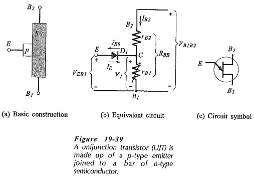
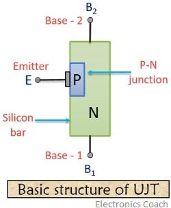
Referred to a bidirectional trigger diode. In a limited region of device operation when voltage. The UJT is made up of a lightly doped n-region known as the base region onto which is joined a small heavily doped p-region called.
But the Ve can be only increased up to a particular point called Vp peak voltage. Between the peak point and the valley point of UJT emitter characteristics we have _____ region A. As the bias voltage at the emitter increases current flows when the bias voltage reaches a threshold or peak voltage at which point the emitter-to.
The terminals of UJT are A. Gate Anode Cathode C. Relaxation oscillator basically comprises UJT and a capacitor that gets charged through resistance by switching ON V BB.
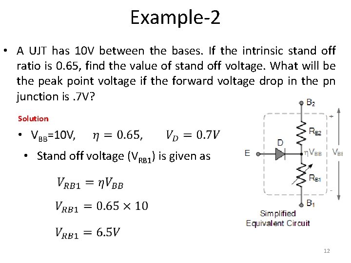
Example 1 Assume that the UJT in Figure 3 has a standoff ratio of 065 and the supply voltage is 200 V. A triac can pass a portion of _____ half-cycle through the load. What is UJT negative resistance.
Total resistance RIS Bulks resistance Interbase resistance The ratio of the emitter to base1 resistance to the interbase resistance of a UJT is called ________. As the Ve is increased the emitter current Ie is also increased and the junction behaves like a typical P-N junction. This allows us to control the conduction angle of the SCR which means the control.
The region where breakover voltage of the SBS drops to 1 V instantaneously. The voltage VR RVBBR RBB for open-emitter terminal. A UJT has _____.
None of the above. If any one supply line is disconnected what is the average load voltage. In a UJT when the emitter voltage is __ than the internal voltage the internal voltage the junction becomes forward- baised.
The voltage across the device decreases in this region though the current through the device increases. The minimum emitter to base voltage to trigger the UJT is the _____. What is the effect an inductor has on current flow.
If the input voltage is 400 Sin 314 t and SCR is fired at find the average load voltage. With the emitter grounded the UJT is reverse-biased and no current flows between base1 and base2. Choose the letter of the best answer in each questions.
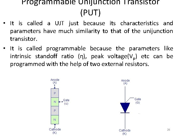
Answer 1 of 2. None of the above. A combination of diac and triac PNPN device A set of SCR diac and triac The peak voltage of a PUT is VD VBB VBB VG VBB VD VG The total internal series resistance of the UJT.
What the unijunction and some other devices offer is negative DYNAMIC resistance. UJT fires when capacitor voltage reaches to the value of peak voltage in time t s immediately discharges till the voltage value decreases to lowermost value Vv As a result the device gets turned off and the. UJT means Uni Junction transistor terminals are EmitterBase1 and Base2UJT is also called double base diodeUJT operates when the emitter is forward biasedvoltage is applied between base1 and.
When emitter voltage V E becomes equal to V p then pn junction becomes forward biased and I E starts flowing. What best describes the term AC effective voltage.
![]()
Unijunction Transistor Ujt
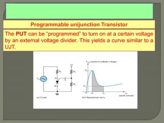
Power Electronics Lecture7 Unijunction Transistor Programmable Unijunction Transistor
![]()
Unijunction Transistor Ujt Comprehensive Tutorial Homemade Circuit Projects
![]()
7 8 The Unijunction Transistor Ujt
Power Electronics Lecture7 Unijunction Transistor Programmable Unijunction Transistor
Ujt Circuit Diagram Ujt Characteristics Ujt Parameters
Ujt Relaxation Oscillators
What Is A Unijunction Transistor Constructional Details Working Characteristics Applications Of Unijunction Transistor Electronics Coach
Ujt Oscillator
![]()
Electronic Note Programmable Unijunction Transistor Put

Unijunction Transistor And Ujt Relaxation Oscillator
Solved The Voltage On The Emitter Of A Ujt Just Before It Fires I Chegg Com

Power Electronics Lecture7 Unijunction Transistor Programmable Unijunction Transistor
Characteristic Curve Of Ujt Electronics Coach
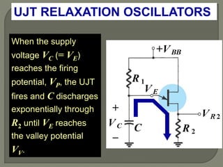
Ujt Relaxation Oscillators

Power Electronics Lecture7 Unijunction Transistor Programmable Unijunction Transistor
![]()
Unijunction Transistor Ujt Instrumentationtools
![]()
7 8 The Unijunction Transistor Ujt

Power Electronics Lecture7 Unijunction Transistor Programmable Unijunction Transistor


